 Finally the right wing was lowered from ceiling storage. I plan to do the
externals first before finishing the interior and controls. Right wing
aileron and rudder are shown cutout.
Finally the right wing was lowered from ceiling storage. I plan to do the
externals first before finishing the interior and controls. Right wing
aileron and rudder are shown cutout.
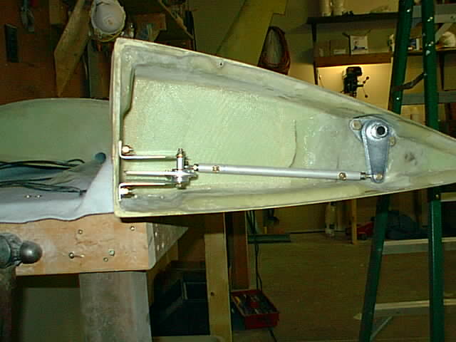
 The aileron controls rod end bearings screw into a bushing which fastens into
connecting rods. The inside end of the steel bushings was solid, so with
my metal lathe I drilled a large hole part of the way into it to decrease
the weight. It may be only a few ounces, but it adds up.
The aileron controls rod end bearings screw into a bushing which fastens into
connecting rods. The inside end of the steel bushings was solid, so with
my metal lathe I drilled a large hole part of the way into it to decrease
the weight. It may be only a few ounces, but it adds up.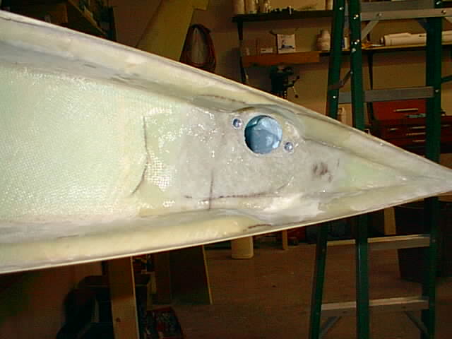
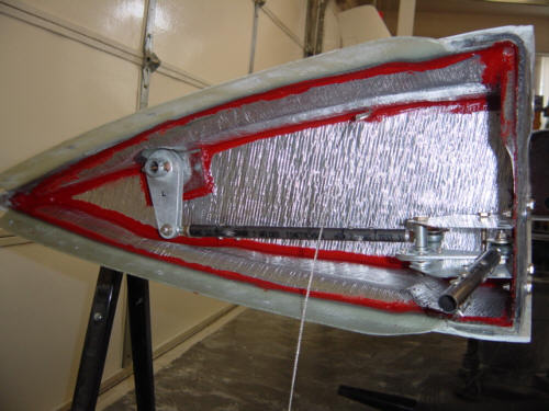
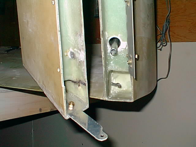
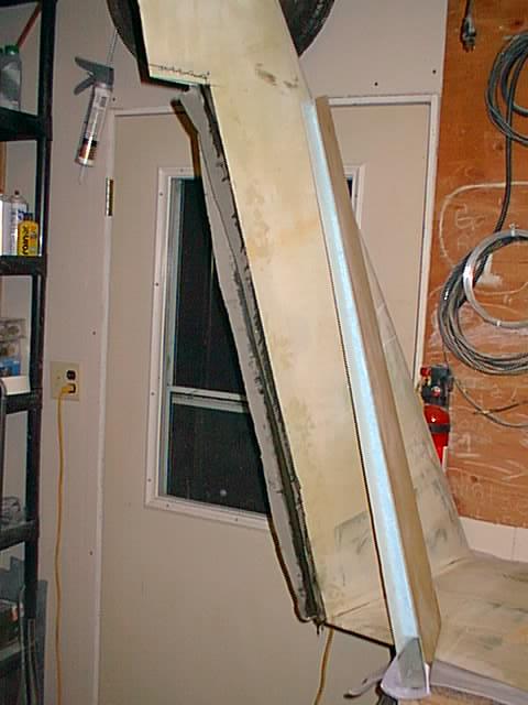
12/14/04 Post build update: If by chance you get the foam wings with your SQ2000, you should install insulation on the wing inboard and front wing flat parts to protect the foam from expansion. When purchasing the SQ2000 kit they gave me a choice between standard braced SQ2000 wings and foam filled wings (foam is used on Long EZ's and Cozy's). But after a few flights I found the inner flat part bulging out and interfering with aileron bellcrank operation. A material called "Thermo-Tec aluminized heat barrier" was used by Berkut builder James Redmon I had to replace the inboard flat part to stop the bellcrank interference and the front part was sanded down and reinforced with a couple of layers of 9oz E-Glass. The right side shown is the worst since that is where the oil cooler is. Long EZ's and Cozy's builder routinely install heat protection on the inner flat part (but not on front flat part) but SQ2000 instructions did not mention the heat protection since the standard wings do not use foam. To stop heat from being blown to the front flat face I will just stuff some insulation in the gap between the wing and spar AND cover the heat exposed spar with some of that Thermo-Tec stuff. You might want to add this heat protection even if you have the regular wings to stop the fiberglass from softening up.
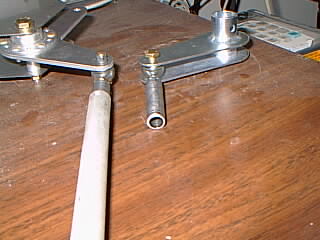
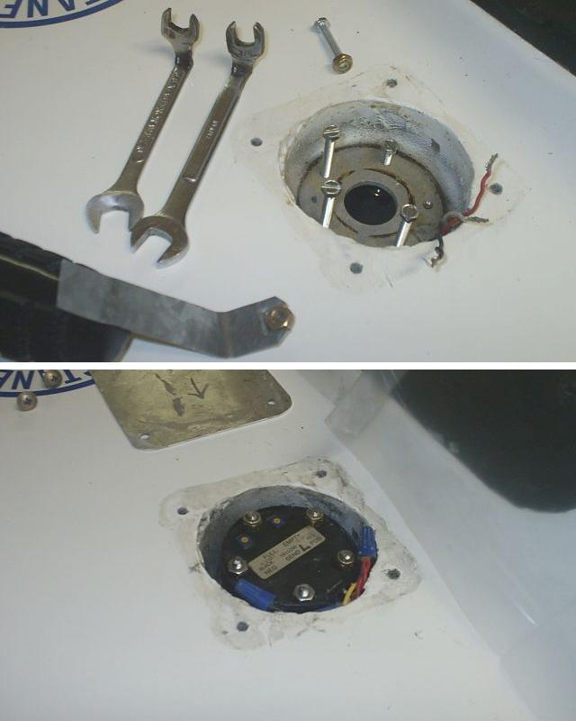
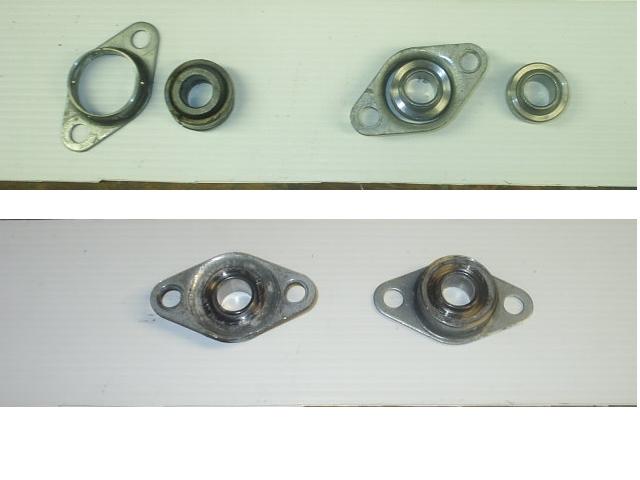 09/14/06 Post build update:
At about 130 hours plane use, ailerons were getting sloppy (due to the
cheap spherical bearings). Replacements were not available in better
bearings (like at infinityaerospace)
with same size housing and bolt dimensions. Replacing them with
something different would be considerable work. So I pressed the old
bearings out of the housing with a vice and purchased new higher
precision spherical bearings from McMaster-Carr (part number 63195K75) These
were smaller diameter than the old ones. I simply filled the gap
between with flox ( well... not that simple.. gotta watch to protect
the inner bearing part from epoxy - have it sitting above a hole that
just fits the spherical ball and protect the top part too. Cover the
board with packing tape for epoxy release.) In the photo top you can
see the original housing and old bearing pressed out and the new
bearing dropped into the housing. The bottom photo shows the finished
product with the new bearings. The flox finish does not look perfect -
but OK as long as you don't get it into the bearing. Use a syringe to
drop the flox between the bearing and housing. Before it gets totally
hard you can clean any touch of epoxy on the bearing with cotton swab
immersed in acetone or other strong solvent - and/or scrape it from
the inner bearing part.
09/14/06 Post build update:
At about 130 hours plane use, ailerons were getting sloppy (due to the
cheap spherical bearings). Replacements were not available in better
bearings (like at infinityaerospace)
with same size housing and bolt dimensions. Replacing them with
something different would be considerable work. So I pressed the old
bearings out of the housing with a vice and purchased new higher
precision spherical bearings from McMaster-Carr (part number 63195K75) These
were smaller diameter than the old ones. I simply filled the gap
between with flox ( well... not that simple.. gotta watch to protect
the inner bearing part from epoxy - have it sitting above a hole that
just fits the spherical ball and protect the top part too. Cover the
board with packing tape for epoxy release.) In the photo top you can
see the original housing and old bearing pressed out and the new
bearing dropped into the housing. The bottom photo shows the finished
product with the new bearings. The flox finish does not look perfect -
but OK as long as you don't get it into the bearing. Use a syringe to
drop the flox between the bearing and housing. Before it gets totally
hard you can clean any touch of epoxy on the bearing with cotton swab
immersed in acetone or other strong solvent - and/or scrape it from
the inner bearing part.
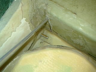
 Showing rudder return spring (on right) inside floxed alum. tube in winglet.
The eyelet bolt in rudder is simply made up of door push rod remnants.
Showing rudder return spring (on right) inside floxed alum. tube in winglet.
The eyelet bolt in rudder is simply made up of door push rod remnants. 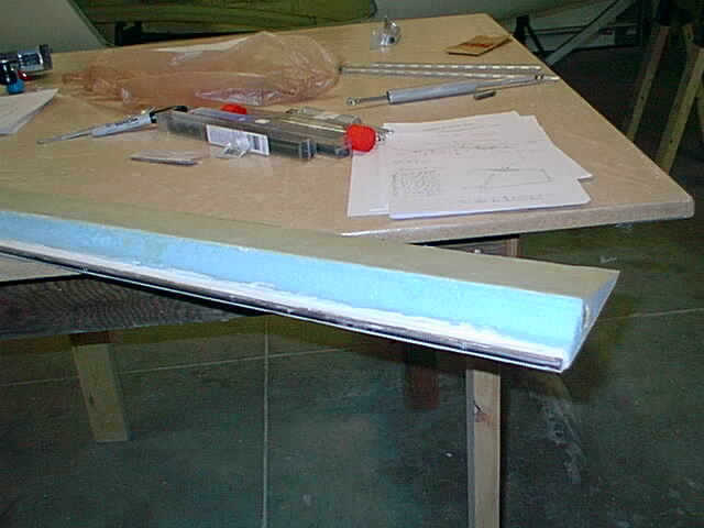 At the factory I got a choice of the standard wing and the foam filled wing which
I chose. The foam filled wings are slightly different to finish off. You carve
out the foam and lay the reinforcement over that. The wings already were
closed off but the ailerons needed finishing. The photo shows the balance weight
microbalooned into place. The hinges are installed somwehat differently from
the standard wings.
At the factory I got a choice of the standard wing and the foam filled wing which
I chose. The foam filled wings are slightly different to finish off. You carve
out the foam and lay the reinforcement over that. The wings already were
closed off but the ailerons needed finishing. The photo shows the balance weight
microbalooned into place. The hinges are installed somwehat differently from
the standard wings.
 OK. Now back to wings (was working on interior and controls but have to wait for
another piece of foam sheet for 2nd attempt on the glareshield).
OK. Now back to wings (was working on interior and controls but have to wait for
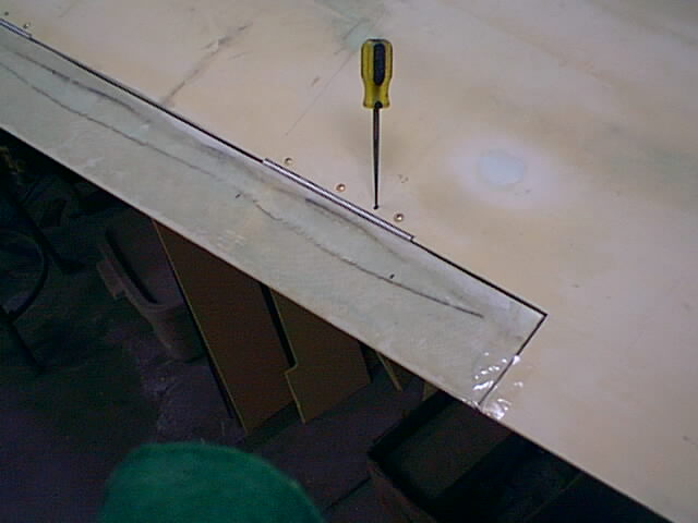
another piece of foam sheet for 2nd attempt on the glareshield).The aileron is shown covered with glass - still needs to be finished smooth. A problem with both rudder and aileron is hinge lineup precission. Irregardless how carefully I measure hinge hole positions, some are still a little out and I have to ream the holes in the wing/winglet to get the hinges to fit. Especially with the aileron, the hinges are inacessible for accurate alignment. To help this I bore an extra hole through the wing and hinge approximatelly where the hinge should be. Then I placed a thin machine screw through that (#6) with washers and slightly tightened. After positioning the aileron, the small machine screw leaves enough room for the hinge to be moved and then tightened into position. After that I drilled the holes for the hinge screws and installed them (still not as precise as I wished). Now the problem part. How do you know where to rivet the aileron hinge half? The position cannot be marked since the hinge is inacessible. What I did is spot flox (not too much) the loose hinge half, moved the hinge half away from the aileron, installed the aileron into position and through the extra hole I pushed the floxed hinge toward the aileron. After curing I can remove the aileron and then install the rivets.
I suppose another way would be to rivet the hinges first to the aileron and then to the wing. But the aileron was not perfectly straight. The hinges then would not necessarily line up on the wing with hinge pins in line.
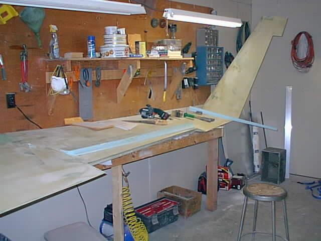
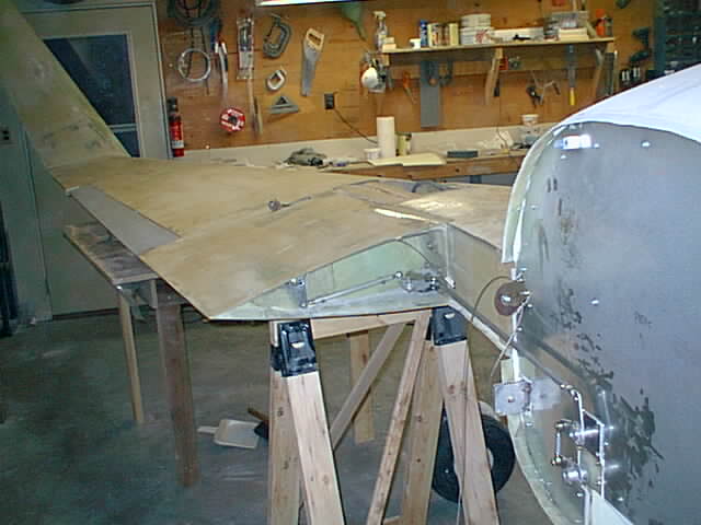
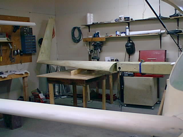 There was a 3 day gap in my construction as I went to Florida Lakeland Sun-n-fun fly in to get more
info from vendors and check some construction details on other canards there.
There was a 3 day gap in my construction as I went to Florida Lakeland Sun-n-fun fly in to get more
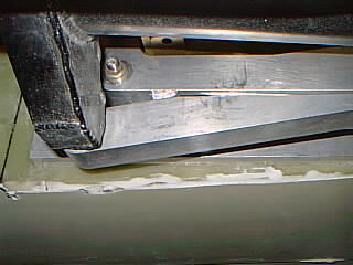
info from vendors and check some construction details on other canards there. Here the fuselage is shown leveled and right wing positioned. The three hard point 1/4" holes have been drilled through the spar before this. The shop (garage) is just large enough to hold one wing in place at a time.
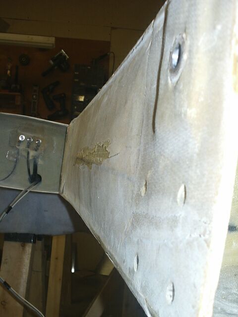
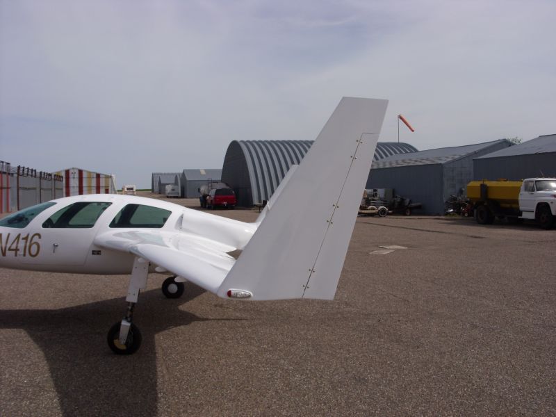
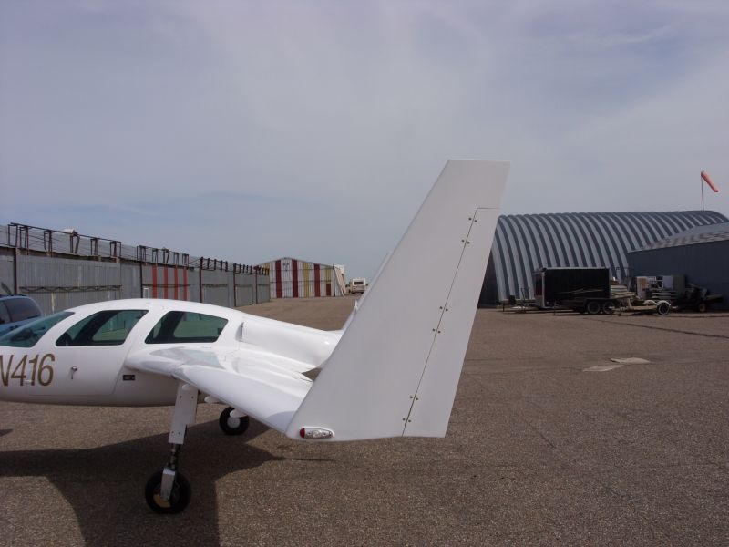
If you do this correctly from begining you will not have the strakes out of whack later when you HAVE to adjust the wing incidence with washers. There is a simple way to get it pretty close (within one washer). Walk to the side of one rudder so that you can see both leading edges of the rudders in sight. See photo1 below. The two leading edges should be parallel. You can do that really close by eyeing the edges closer - see photo2 below. The process is more accurate when viewing live than photos illustrate. The method worked for me (albeit after strake construction) and it should work for you since I assume SQ2000 wings come from the same mold. (Click on photo to enlarge.)
Do this before mounting strakes so the strakes will be inline with wings.
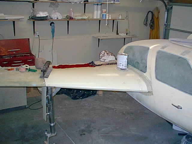
 And now working on the left wing - rudder cuttout and glassing in the opening.
The wings I got were foam filled so that I had to remove some foam to glass in the
opening. Microballoon mixture helped round out rough spots in foam.
And now working on the left wing - rudder cuttout and glassing in the opening.
The wings I got were foam filled so that I had to remove some foam to glass in the
opening. Microballoon mixture helped round out rough spots in foam.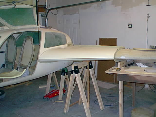 Wings bolts & bushings positions drilled. Left wing bolted & leveled, now starting work on left strake.
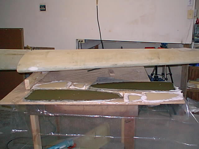 Glassing both sides of strake ribs before trimming to final size. The instructions did
not indicate this, so an email to the factory was necessary to find out.
Glassing both sides of strake ribs before trimming to final size. The instructions did
not indicate this, so an email to the factory was necessary to find out. I ran out of peel ply and the the dark green color is the "new" peel ply material I got from Wall-Mart on sale for $1/yard. This one happened to work - hard to find smooth Dacron in stores.
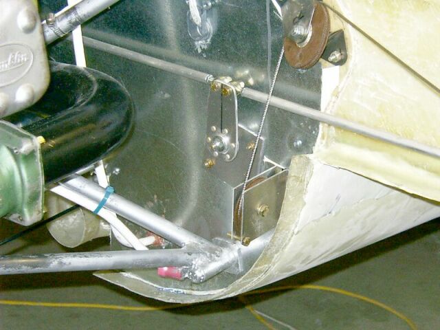
 Glassing LS lower strake into position.
 From factory I found that the up position should be
adjustable with the rod end bearing on cylinder. But that did not
work with the LS RG. Had to cut the mid strut mount bracket and
reposition/weld it after which it could be adjusted. The RS
was found to adjust OK.
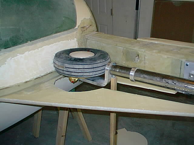
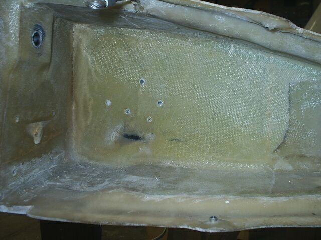
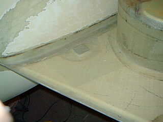
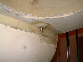
In the first photo below you can also see a 1/4" foam piece (omitting the fuel cap area) glassed on top of the wheel well to give more rigidity to the flat surface to resist the fuel load on top.
The third photo shows the the went line as per factory drawings - going
through the spar. That was removed later and the vent was routed from
the gas cap position right into the fuselage and around the window and
then back to the firewall as can be seen in interior layout
and down below in the fuel tank sealer photo.
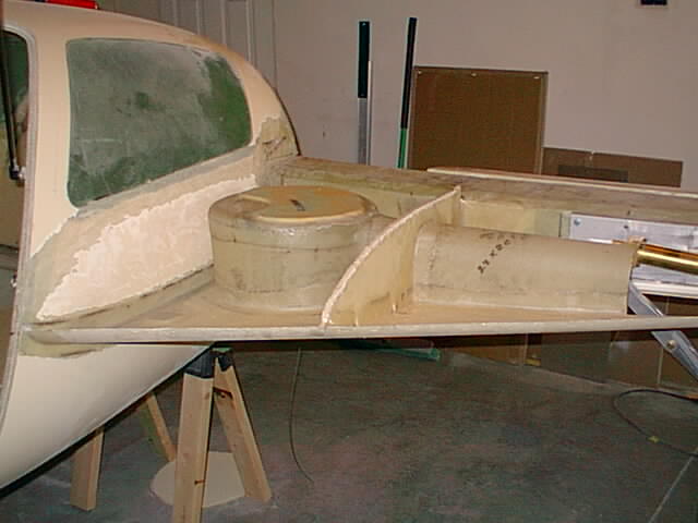
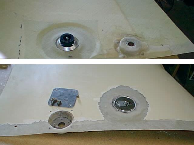 Upper strake part: showing fuel cap and fuel sensor depression, "box" (outside/upper aluminum cover shown) glassed in.
The fuel sensor box has another small glassed in "box" for wire conection area
and hole leading to over the spar for the connecting wires.
Upper strake part: showing fuel cap and fuel sensor depression, "box" (outside/upper aluminum cover shown) glassed in.
The fuel sensor box has another small glassed in "box" for wire conection area
and hole leading to over the spar for the connecting wires.
 12/22/04 Post build note: While I covered the cover nuts above with fuel sealant I did not
do that for individual screws holding the fuel sensors down. I figured the gasket would be enough.
Nobody told me otherwise.
But during testing I found that when tank is full the fuel worked its way up the screw threads.
I tried removing the screws and sealing them with gasket sealant and tightening them better.
That still did not prevent seepage and I also ruined a couple of aluminum threads in the sensor mounting plates.
Eventually I found a solution: Removed the screws and installed temporary longer ones on the bottom
of which (using special reach in the the hole tools) I mounted locknuts. The bottom of the
thread and above the locknuts I dabed with fuel tank sealant goo and tightened the nut/screw upward.
The bottom of the locknuts was also gooed after tightening. That provides a seal to prevent fuel
going up the screw threads. I cut off the screw heads tops and installed new gaskets
and the sensors sliding them over the studs. Then tightened the sensors down by
installing nuts on top. Two of the studs were relatively loose because of the bad
threads in the aluminum plate and I had to use non-locknuts to prevent rotating
the studs after sealing them - I used LockTite thread lock instead.
12/22/04 Post build note: While I covered the cover nuts above with fuel sealant I did not
do that for individual screws holding the fuel sensors down. I figured the gasket would be enough.
Nobody told me otherwise.
But during testing I found that when tank is full the fuel worked its way up the screw threads.
I tried removing the screws and sealing them with gasket sealant and tightening them better.
That still did not prevent seepage and I also ruined a couple of aluminum threads in the sensor mounting plates.
Eventually I found a solution: Removed the screws and installed temporary longer ones on the bottom
of which (using special reach in the the hole tools) I mounted locknuts. The bottom of the
thread and above the locknuts I dabed with fuel tank sealant goo and tightened the nut/screw upward.
The bottom of the locknuts was also gooed after tightening. That provides a seal to prevent fuel
going up the screw threads. I cut off the screw heads tops and installed new gaskets
and the sensors sliding them over the studs. Then tightened the sensors down by
installing nuts on top. Two of the studs were relatively loose because of the bad
threads in the aluminum plate and I had to use non-locknuts to prevent rotating
the studs after sealing them - I used LockTite thread lock instead.
 The gray fuel tank sealer compound is a bit smelly stuff (not terrible). The LS strake is finally
getting ready to close in. There have been many details here before deciding the exact
way of doing things. The smaller wheel well does not have a lot of clearance from wheel.
So I wrapped a 1/4" foam around it with two layers of S glass. That gives an extra
1/4" + room if the wheel should rub the strake and it could be fixed from outside.
The factory original wheel well is 17" diameter and after my inquiry they sent me
14 1/2 inch wheel wells which just barely are larger than the 13 1/2 inch
dia wheels. The 17" ones seem a little too large and would have a difficult time
fitting in the strake. I think 15" would be ideal.
The gray fuel tank sealer compound is a bit smelly stuff (not terrible). The LS strake is finally
getting ready to close in. There have been many details here before deciding the exact
way of doing things. The smaller wheel well does not have a lot of clearance from wheel.
So I wrapped a 1/4" foam around it with two layers of S glass. That gives an extra
1/4" + room if the wheel should rub the strake and it could be fixed from outside.
The factory original wheel well is 17" diameter and after my inquiry they sent me
14 1/2 inch wheel wells which just barely are larger than the 13 1/2 inch
dia wheels. The 17" ones seem a little too large and would have a difficult time
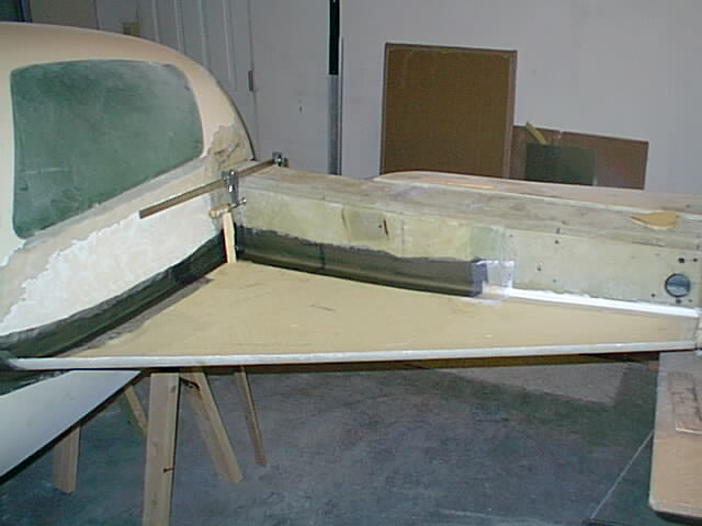
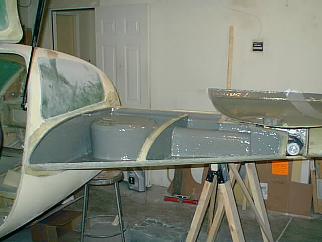
fitting in the strake. I think 15" would be ideal.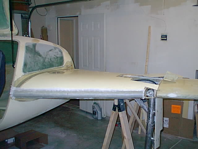 And finally the strake/tank is closed in. I had problems with a faulty hydraulic cylinder
rod end bearing breaking and decided that I would not close
the area above the hydraulics in permanently but made it a removable piece.
That makes maintenance easier than attempting just to get at things from bottom.
And finally the strake/tank is closed in. I had problems with a faulty hydraulic cylinder
rod end bearing breaking and decided that I would not close
the area above the hydraulics in permanently but made it a removable piece.
That makes maintenance easier than attempting just to get at things from bottom.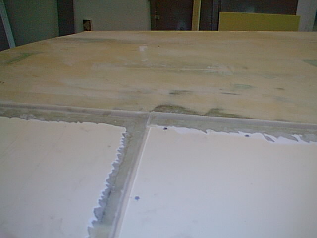 Strake/Wing fairings: I covered the gaps by glassing thin strips over them and attaching
them only to the upstream part. That way the pieces are removable for maintenance
and the gaps are covered. Using caulk will require re-caulking each time maintenance
is performed.
Strake/Wing fairings: I covered the gaps by glassing thin strips over them and attaching
them only to the upstream part. That way the pieces are removable for maintenance
and the gaps are covered. Using caulk will require re-caulking each time maintenance
is performed.
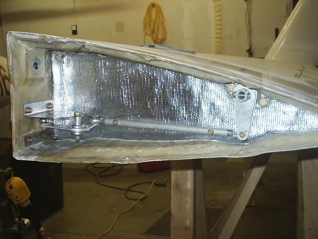
 LS aileron hinges and mechanicals installed.
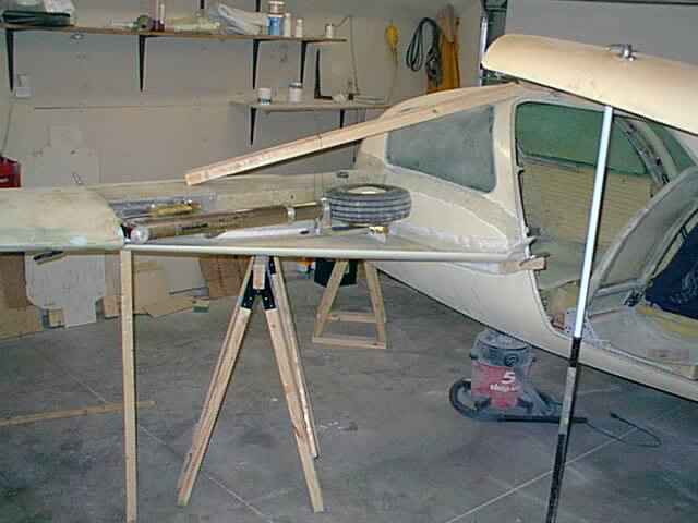 And now puting in the right side strake. This really goes faster now knowing
what to do.
And now puting in the right side strake. This really goes faster now knowing
what to do. The diagonal 2x4 wood on top holds the RG away from the strake with a wire which is barely visible.
OK. After finishing the RS strake I will need the engine/prop/cowling, the remainder of control connections and then fill-n-sand and paint. It may happen all this fall. Interior upholstery may be neglected somewhat untill later. May just ride on a covered foam cushion.
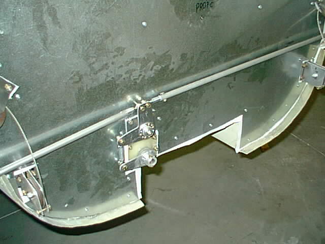
03-30-03 Aileron rod update: The RS of aileron rod was rubbing against the rudder cable
in extreme positions. I installed a second rider belcrank to keep the rod away
from the cable.
 Showing placing of RS strake top after the binding flox layer was spread on top
of the spar. The flox generates so much heat that I placed some wet towels on
top to slow down the reaction. I laid the flox with a release tape
below the strake top to remove the top later. This allows placing an additional
glass strip on the front flox layer and spar surface. Requiring a thin layer of flox later
also allows precision laying of the strake top.
Showing placing of RS strake top after the binding flox layer was spread on top
of the spar. The flox generates so much heat that I placed some wet towels on
top to slow down the reaction. I laid the flox with a release tape
below the strake top to remove the top later. This allows placing an additional
glass strip on the front flox layer and spar surface. Requiring a thin layer of flox later
also allows precision laying of the strake top.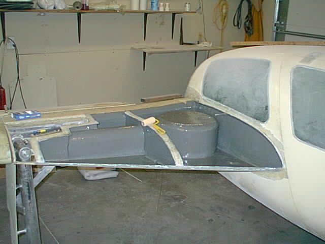 Applying fuel tank sealer to bottom part of RS strake. There does not seem to be a lot
of tank sealant resin left to finish the job and I was afraid that I would run out.
So I used a small roller to help me spread the stuff more evenly and thiner (3 coats
are required) and just managed to have sufficient material with a few grams left over.
I would have run out if I used a brush only as permitted by factory recommendations.
Guess I'll mix the remaining stuff together to have it harden to avoid disposing of
liquid chemicals. I do the same thing with resin containers - put in a little hardener
to have it set so it is not a hazard.
Applying fuel tank sealer to bottom part of RS strake. There does not seem to be a lot
of tank sealant resin left to finish the job and I was afraid that I would run out.
So I used a small roller to help me spread the stuff more evenly and thiner (3 coats
are required) and just managed to have sufficient material with a few grams left over.
I would have run out if I used a brush only as permitted by factory recommendations.
Guess I'll mix the remaining stuff together to have it harden to avoid disposing of
liquid chemicals. I do the same thing with resin containers - put in a little hardener
to have it set so it is not a hazard.